Recirc system technology
Part 1: Solids removal, biofiltration
From market size tilapia to shrimp maturation, applied recirculating aquaculture systems (RAS) employ many common processes, but with different apparatus and different process objectives.
Shrimp maturation systems require extremely high-quality water with extremely low, if not undetectable, nutrient waste levels, including ammonia, nitrate, and nitrite. This leads to an emphasis on large filters with extremely large biofilter surface areas, such as fluidized sand bed filters (FSBs).
Tilapia, on the other hand, are significantly less demanding in that they can tolerate higher nutrient waste levels and even survive brief periods of poor water quality that would be lethal to many other species.
This tolerance has facilitated much progress in the development of RAS technology because interest in increasing system intensification has prompted engineers and growers to focus on other limiting processes, such as fine solids removal, CO2 stripping, and oxygenation. Solids removal systems design and large capacity biofilters remain the focus of RAS research and development activity.
Several years ago, Dr. Tom Losordo of North Carolina State University presented a basic "fish model," which summarizes the key inputs and outputs in feeding and growing fish (Figure 1).
From this model, it is easy to arrive at the following list of critical/fundamental RAS processes:
-
Solids removal;
-
Foam fractionation;
-
Ozonation;
-
Biofiltration;
-
Aeration/ CO2 stripping;
-
Oxygenation;
-
Economics; and
-
Management.
Solids removal
By far, one of the most demanding and contentious areas of RAS process technology design is the removal of suspended solids. According to Losordo's fish model, we end up with a 1/4-pound or more of solid waste for every pound of feed that we provide the fish.
The most effective water treatment process is "avoidance." By quickly removing solid waste from the fish culture system, we avoid costly treatment of this waste after it has degraded physically, chemically, and biologically.
| Fig.1 Fish Model |
|
. . . Inputs: |
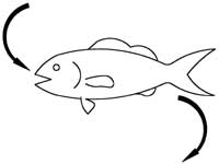 |
| . . . Inputs: . . . . . . 1/4 to 1/2 pound of waste solids . . . . . . 1/4 to 1/2 pound of CO2 . . . . . . 2/100 o 3/100 pound of ammonia |
Let's take a look at a production facility that yields one million pounds of fish per year. With a not-so-aggressive feed conversion ratio (FCR) of 1.5:1, we would be providing:
-
1.5 pounds feed (dry weight [wt])/pound fish (wet wt) x 1,000,000 pounds fish (wet wt) = 1,500,000 pounds feed (dry wt) per year; and
-
Solid waste (dry wt) per year = 0.25 x 1,500,000 pounds (dry wt) = 375,000 pounds (dry wt) per year or roughly 1,000 pounds of solid waste (dry wt) per day.
If we attack this problem with shovel and bucket, we are most definitely doomed to failure. Large fish production systems might attack this problem with circular growout tanks equipped with "double drain" tanks, swirl separators, and rotating microscreen drum filters.
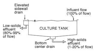
A double drain system such as the Cornell University double drain tank (Figure 2 next page) allows one to separate the majority of the accumulated solids within a small minority (1%-20%) of the system turnover flow stream.
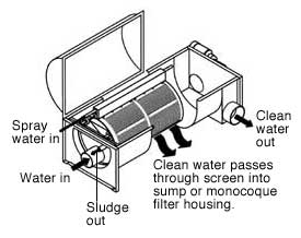
A swirl separator will remove the readily settleable solids such as uneaten feed and fecal pellets. Depending on screen size, the microscreen drum filter (Figure 3) will effectively remove solids down to 20 microns or so.
For our larval water quality system, such as that used for shrimp maturation, we might simply use a bead filter (Figure 4) upstream of our fluidized sand bed filter.
Foam fractionator
However, as we push the level of intensification, which increases stress on our fish, and we reduce the dilution effect of replenishment water by reducing same, we come to appreciate the fact that on a particle count basis, we must remove a large percentage of very fine particles, <30 microns, from the system. These fine particles degenerate chemically and biologically and irritate fish gills, which leads to increased stress and bacterial infections.
On a small, side-stream basis (approximately 25% of system turnover rate), we can remove these fine suspended solids with a foam fractionator (Figure 5), which is also known as a protein skimmer.
Foam fractionators use millions of fine coalescing bubbles to grab these fine particles as well as other dissolved organics and float them out in a waste-laden foam.
Ozone-enriched air is often used as the feed gas, especially with freshwater systems. Ozone breaks down organic material and improves the coalescing and foam production processes. The disinfection effect of ozonation is an added benefit.
Nitrification
As the fish model illustrates, we get a small percentage of ammonia from our fish as a result of it ingesting and digesting that pound of feed we provided. This ammonia will exist in both the ionized and un-ionized form, the ratio of which will depend on the pH of the water medium.
The bad news is that the un-ionized form is extremely toxic to the fish. The good news is that we can minimize the percentage of ammonia in the un-ionized form by adding alkalinity and maintaining system pH slightly above 7 (slightly basic).
Biofiltration, which is also referred to as nitrification, is the process that uses naturally occurring and sometimes selected bacteria to convert ammonia to a less toxic nitrogen compound. That is, bacteria converts the ammonia to nitrite and bacteria converts the nitrite to nitrate.
Depending on the fish species, nitrite is relatively intolerable and nitrate is tolerable in the range of 200 ppm. With ammonia tolerance somewhere in the 1 ppm neighborhood, we must provide enough nitrification, i.e., bacteria, to convert our ammonia production to nitrate. With minimal replenishment water, on the order of 10% or less of system volume per day, we can dilute the nitrate level to keep it in a tolerable range.
The trick for achieving effective biofiltration is to provide appropriate real estate, in both quality and quantity, to accommodate a very large population of nitrifying bacteria. The crux of biofilter design is to provide this real estate with appropriate quality and quantity in a cost effective manner.
| Fig 2: Cornell Double Drain Tank | Fig 3: Microscreen Drum Filter | |
 |
 |
|
Biofilters
The most common biofilters can be categorized as five basic types, which are described as follows.
Rotating biological contactors (RBCs) RBCs were developed in the domestic wastewater treatment industry and are fairly widely used in aquaculture.
The RBC uses a biofilter medium attached to a rotating shaft. The unit is partially submerged, which causes the media and nitrifying bacteria to be alternately exposed to air and then resubmerged in the nitrogen rich fish water.
While the design is simple and aeration and degassing are inherent co-processes, there are some major disadvantages, including high installation costs and mechanical failure due to the heavy weight of the contactor and the biological growth that covers the filter media.
Trickling filters These filters have also evolved from the domestic water treatment industry. Filter media with a relatively low specific surface area (square feet per cubic foot of media) is placed in a reactor vessel with a water distribution plate at the top.
| Fig 4: Bubble Bead Filter |
The filter is configured to operate in a nonflooded configuration and, so, provides nitrification, aeration, and some CO2 stripping. The low specific surface area and the relatively high cost of this media limits this application to small, lightly loaded systems. Expandable media filters These include bubble and propeller-wash bead filters. These units typically operate as upflow filters and, because of the tight pack of the relatively small plastic beads, provide both solids capture and nitrification.
|
With specific surface areas on the order of 400 ft2/ft3, this kind of filter will handle approximately one pound of feed per day per cubic foot of media.
In the right application, the combined solids capture and nitrification functions are a good fit. It is argued, however, that the economics of large production systems justify the separation of these two processes. This argument is based in part on the degradation of solids trapped within the bead bed that occurs during the relatively long period between backwash cycles (1-48 hours). This degradation creates ammonia and consumes oxygen, both of which impact nitrification capability.
Fluidized sand bed filters These filters are basically sand filters that are operated continuously in the expanded or backwash mode. Thus, there is no solids capture, but then the unit does not gel up if operated continuously.
Unlike FSBs, pressurized down-flow sand filters tend to create gelatinous, bacterial masses that eventually become impossible to clean or backwash. The fluidized sand bed is an excellent media for growing nitrifying bacteria.
Specific surface area is phenomenal on the order of 10,000 ft2/ft3. Many large production systems look to fluidized sand bed filters to provide the most cost effective nitrification process. Published literature indicates that fluidized beds will handle up to 2.5 pounds of feed per day per cubic foot of media (sand).
Mixed bed reactors These filters are a relatively new approach that combines upflow bead filters and fluidized bed filters. These filters use a small, light plastic media, such as the Kaldnes KMT media, which is kept in a continuous state of movement (up, down, and/or around) by either hydraulic or mechanical means.
|
Specific surface area is approximately 300 ft2/ft3. Published literature indicates that the mixed or moving bed reactor will handle 1.0 to 1.4 pounds of feed per day per cubic foot of media. Vital roleSome people will argue that solids management and removal are the most important RAS process technologies. Up to one-half of the "load" of feeding and growing fish in a recirc system can be handled or avoided through proper implementation of these management processes, while, at the same time, reducing the size and enhancing the performance of one's biofilter. |
Fig 5: Foam Fractionator |
Sounds like a good argument to me.
Nonetheless, the biofilter is still a vital "organ" in a recirculating aquaculture life support system that finishes off the waste treatment work started by the solids removal system.
More on how recirculating aquaculture systems handle CO2 stripping and oxygenation next time.
Paul Hundley is president and principal engineer for Applied Aquatics Inc. in Charleston, SC. He has more than 25 years experience in the design, construction, and operation of commercial, industrial, and institutional facilities and has been working in aquaculture for over 10 years.
Hundley can be reached via: phone (843) 971-9639; fax (843) 971-9641; or e-mail [email protected]. Copies of this and other Systems Engineering articles are available at www.AppliedAquatics.com.
Note: Some of the information contained in this article has been generated by independent sources. Such information is accurate to the best of the author's knowledge, but the author disclaims any liability for the accuracy or completeness of such information or the reliance by any party on such information. Reader comments and corrections are welcomed.

Please contact
Fish Farming News for reprint information
and permission. - © Compass Publications, Inc.,
2000